Features:

Understanding classic logic ICs — a series
Need one of these? (early decoder)
The SCI 1000 — orphan no longer


Those #^*%@! Bipolar Monolithics


Q: When is RTL not really RTL?

A: When it's on a chip, silly!

You should have guessed that one, right?

Several years ago, National Semiconductor made news by spinning off its standard logic products division into a new company called Fairchild Semiconductor. The name was not chosen at random, because the then-new Fairchild was, by a long and tortuous process, related to that division of Fairchild Camera and Instrument Corp. which, in the mid 1960s, introduced what many consider the industry's first consumer-priced digital IC family. Fairchild, a pioneer producer of discrete silicon planar transistors, had popularized a low-cost, molded, epoxy package with the same footprint as the venerable TO-5. Much to no one's surprise, they found that adding a few more leads to the traditional three-lead circle yielded a cheap, useable and reliable package for more complex dice with eight or ten terminal pads. When Fairchild's popular diffused-junction planar transistors and diodes and resistors, all tied together by a deposited aluminum interconnection layer, met the new package, the µL900 family was born, and the rest, as they say, is history.

Within months, widely read magazines like Radio Electronics and Electronics World began featuring construction project articles with circuits designed around the 無914, a dual, two-input NOR gate which rapidly became one of the hobbyist market's most coveted components. This erstwhile logic chip thus found its way into projects ranging from microphone preamp/mixers to video pattern generators; this flexibility of application owed much to the chip's extreme internal simplicity, as did its high manufacturing yield and low cost.

About the same time, another silicon transistor powerhouse — Motorola Semiconductor — introduced an economical “RTL” IC family, the MC700P series. Exploiting another brand-new package type, the 14-pin plastic DIP (dual-inline package), this series achieved a slightly higher level of integration with its larger dice, accommodated by the DIP's higher pin count, exemplified by a quadruple two-input NOR gate (MC724P), a hex inverter (MC789P) and a dual JK-type flip-flop (MC790P). In an era when typical ICs were outrageously expensive, the MC7XX's low prices (the gates and inverters listed at $1.08 each, quantity one, in 1968) made them a big hit with consumer-products design engineers and hobbyists alike.

As you can see from the 無914 schematic at right, this four-input, two-output circuit contains a grand total of four transistors and six resistors. Its functioning as a logic circuit is simplicity itself: if either input A1 or B1 is driven to the High (logic “one”) level, the corresponding transistor saturates, and the voltage at its collector — which happens to be output Z1 — drops to around 0.2 volt, which is the Low or logic “zero” level. Of course, the same applies to output Z2 with respect to inputs A2 and B2. As for its functioning in audio and other non-digital systems, almost anything you can do with ordinary NPN transistors with grounded emitters and collector loads in the 600-ohm range is fair game, especially if you can use two transistors in collector-emitter parallel.

So, if a logic circuit is made up of resistors and transistors, why not call it “resistor-transistor logic” — RTL, for short? One good reason is that that name had already been in use for some years to refer to a rather different type of logic circuit made with discrete transistors. (The Motorola folks, to their credit, used the name MRTL for their “RTL” product family.)

Now, this is RTL: a six-gate circuit made by Hazeltine for Western Union.


In the schematic at right is an example of real RTL, a NOR gate with four inputs. This is among the cheapest (and, unfortunately, the slowest) types of logic one can build with discrete components, requiring only one transistor per gate; the corresponding monolithic “RTL” circuit has four. On a chip, additional transistors don't cost much (unless including them makes the die too large), but in discrete designs, transistors are typically the costliest components.


At a rather gross level of detail, this circuit behaves much like the 無914 circuit above — if any one of the inputs is driven to a sufficiently high positive voltage, enough current flows through the input resistor into the base of the transistor, causing it to conduct heavily, so that the output voltage is quite low, and if the transistor is saturated, then additional high inputs won't affect the output (desirable behavior for a NOR gate, after all). But if the other inputs are pulled down to a Low level (near ground), then some of the current entering through the High-driven input is siphoned off to ground through the other input resistors and the outputs of other gates.

In “classical” RTL system design, resistor values were often calculated with reference to the entire system. Considering a multi-level network of gates like the one shown, one quickly recognizes that the collector pull-up resistors of the gates at level k and the input resistors of the gates at level k+1 may constitute a rather complex resistor network. Fortunately, each of these level-interconnect networks may be treated without regard to any of the others, provided that the transistors always saturate when conducting (which can easily be arranged) and that the network levels are “pure” (i.e., every input to a gate at level k+1 is driven by an output from level k). But real-world systems are rarely so simple. Typically, there is a gate in level four, say, that uses outputs from levels one and two as well as three, and the simplifying assumptions go out the window. Classical RTL design is not for the faint of heart.

So what do we make of the Fairchild/Motorola style of “RTL” (or, if you prefer, RT無/MRTL)? What is it, really?

The answer to this question becomes clear when one recognizes that the input resistors are too small to be of much use in RTL circuits of the classical type — they're typically about 450 ohms, vs. several thousands of ohms in classical RTL — and compared with about 600 ohms for the collector pull-ups. So if Vcc is at a standard level of 3.6 volts, an unloaded gate pulling its output Low has about 5 mA flowing into at least one collector, which requires roughly 250 渙 into at least one input. The manufacturers recommend, however, that the fanout (the number of inputs driven by a single output) not exceed five, so in that (worst) case, each input resistor drops only about 0.4 volt. If you've been keeping score and you're tempted to conclude that the logic “High” at a fully loaded output may be only about one volt, then pat yourself on the back.

One would think that the purpose of the input resistor might be to limit the base current so that the voltage at the collector of the driving gate won't sag so low. For example, in the case of the Hazeltine product pictured, the pull-up is 1000 ohms and the input resistor 5600 ohms. But in the 無914 or the MC724, the loaded High output voltage may drop to a volt or even less.

The point is that the effect of these small input resistors on base current is not so much restricting as “leveling” — i.e., enforcing uniformity. If the resistance were reduced to zero, then an output driving multiple inputs would be connected to several transistors' base-emitter diodes in parallel, which is a basic no-no in transistor circuit design, as the exact base currents drawn by individual transistors — even of the same type — may vary wildly. The standard solution to this problem is to insert a small resistance in series with each base, and that is precisely what was done in the 無914 and MC724.

Understanding that apart from their current-leveling function these input resistors aren't needed, we can easily recognize the true nature of this circuit: it is not resistor-transistor logic but direct-coupled transistor logic (DCTL), beloved of many designers of high-performance logic in the late discrete-component era (most famously, Seymour Cray). DCTL circuits are noted for their simplicity and their relatively high speed when constructed of suitable transistors, despite their reliance on saturation (more about that later).

Good saturated switching transistors are essential for DCTL, because the difference between the voltage drop of the base-emitter diode (VBE) and the collector-emitter voltage in saturation (VCEsat) establishes the difference between High and Low logic levels, which determines the noise margin. Consequently, germanium transistors are hardly ever used in DCTL circuits, since their low VBE (around 0.3 volt) severely compresses the logic levels, decimating the noise margin. A 2N3576, on the other hand, has VCEsat of 0.15 volt (maximum) at 10 mA, which contrasts nicely with its corresponding VBE of 0.75 volt (minimum), yielding a worst-case level differential of 0.6 volt, which is not bad for DCTL.

So integrated-circuit RTL is really DCTL. But hey, it works.


Next: DTL


Need one of these?


Before there were diode matrices there were...

... (UGH!) transformer matrices. This one is a “CPA MAGNETIC TRANSLATOR", and the silk-screened PN is 677C478 G1. It was made by GE, and the foil revision date is 6/18/58. The fab date is unknown, but it can't be much later.

What you see is pretty much what you get: 130 little toroids and a complex, intricate interweaving of magnet wire. That and 33, 10-ohm resistors. All told, a special-purpose pulse transformer matrix designed to decode something into something else, but I don't know just what. A friend suggested it might have come from a GE 225. Anybody out there have a 225? Does it have one of these in it? Do you need a replacement for it?

Anyone who's interested in this little jewel is cordially invited to send info, comments, whatever: send a message


Orphan no longer!


Good news! The SCI 1000 has found a new home. It's still an interesting old machine, however.

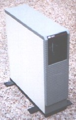
Though only about 40 years old, the SCI 1000 enjoys a place in hardware history not only as a quaint reminder of the friendly, tranquil neighborhood we enjoyed before Microsoft moved in, but also as a wild steer that broke away from the herd.

It's amusing to reflect that, while the growing popularity of Linux at present is viewed by many as a fairly recent development, the first half of the 1980s was rife with little Unix boxes aimed not only at technical users but also at business enterprises, especially small ones. Seventh-edition Unix and its early descendents, with their modest resource requirements and clean, powerful terminal handling, gave these machines the simple, efficient time-sharing environment they needed to meet the basic computing needs of a small-office user population.


Of course, the venerable PDP-11 (notably the /70) was a formidable competitor, but these economical “tower” systems, apparently inspired by the discovery that adding serial ports to a Sun yielded a machine capable of serving numerous terminals, came from several makers, many with names now generally forgotten. The new 16-bit processor chips fueled this revolution; not the LSI-11 or the Microflame, though. They were the newer architectures, like the Motorola 68000 and 68010, the Zilog Z8001, and the National 16032 (later called 32016). But Intel's products were largely overlooked in this venture, except at SCI Systems of Huntsville, Alabama, where the 80186 was chosen to power the SCI 1000.

The SCI 1000 is a flyweight by modern standards; its 1 MB of RAM (though quadruple that of the PDP-11/60 on which your humble scribe did much of his hacking four decades ago) and 40 MB disk wouldn't go very far running today's PC applications. But it came with Interactive Systems' port of Unix System III and an early edition of the Informix database management system, and with eight RS-232 serial ports, it really did support eight terminals running database queries and reports, markup-style word processing with vi and troff, spreadsheets (using sc) and the like. And, as you'd expect in a commercial-grade machine, it offered easy and reliable backup via a QIC-02 tape drive. It also featured a 5.25-inch diskette drive and standard parallel printer port.

Actually, it isn't hard to explain why Intel processors didn't figure in the early-1980s Unix-box boom. The 8086, 80186 and 80286 are irremediably 16-bit machines, and the former two support only 1 MB memory spaces. Even the '286 with its 24 bona fide address bits is hog-tied by the 64-KB segment model. Of course, you can have a 256-KB segment if you can confine the text to one quarter of it and the stack to another quarter and all pointer targets to the same quarter and if you don't use string primitives and if you can guarantee that arrays never overlap 64-K boundaries and if you don't mind that half your text consists of segment prefixes. But not many large, real-world programs fit into that straightjacket. Then to top it off, the '86 and '186 require outboard protection hardware.

Well of course, the PDP-11 had similar drawbacks, and it did support V. 7, System III and 2BSD. Even the IBM PC/XT with its unprotected 8088 ran a version of System III which IBM released in early 1984 under the name PC/IX, as well as SCO's V. 7 derivative Xenix. But the trend was toward more powerful (hence bigger) applications and bigger kernels. Everyone could see that System V and 4BSD were the way forward.

So the 68000 was a natural, because though implemented with 16-bit data paths inside and out, it behaves like a 32-bit machine with its 32-bit registers and 24-bit homogeneous (i.e., “flat-model”) addressing. To that, the 68010 added bus-cycle restartability to support page fault handling. Similarly, NSC's 16032 (later 32016) was the 16-bit-bus version of the 32032, the industry's first monolithic 32-bit CPU.

It isn't widely recognized, but even the Z8001, with its quite thoroughgoing 16-bit architecture, could support 32-bit systems. For all its simple 16-bit registers and data paths, its instruction set extended double-word orthogonality even to multiplication and division, one-upping the 68000. Its memory addressing scheme is regarded as 64KB-segmented in view of its 16-bit “offset” fields and 16-bit registers, but it blissfully lacks segmentation-enforcing features like the segment-base registers of the 8086 and the segment descriptor vector indexing of the protected-mode 80286. The Z8001 simply presents a segment ID on seven package pins (ergo it has 48 pins, compared with the Z8002's 40), and this value may be handled with great sophistication by external logic, but in typical cases (including one product manufactured by Zilog) it is merely treated as seven more address bits. It turns out that the register indirect addressing mode can yield 8-MB, flat-model indexing via a simple coding trick which is easily incorporated into a compiler's code-generator phase. Of course, PC-relative jumps are potentially hazardous in large programs, but that problem is also easily dealt with when the compiler allocates memory using a page-oriented model, as is typical of compilers used under 4BSD-derived systems.


Don't forget that we have lots of hard-to-find vintage components waiting to play important roles in your computer restoration project. E-mail or call us and let us know how we can help. Even if we don't have what you need, we can often help you find it.


Return to home page